Autodesk Inventor - Creating Secondary Flange Features - Contour Flange
Secondary Flange Features
Creating Secondary Flange Features in Autodesk Inventor
Contour Flange:
The Contour Flange creates a Contour Flange on a face.
To create a Contour Flange:
Create a sketch on the edge on the Face.


Width Extends
Width Extends only works if you select one edge.
Edge
Places the Contour Flange all the way along the edge you have selected.

Width
Centered (Width)
Places the Contour Flange in the middle of the edge you select. Then the width of the Contour Flange is determined by the dimension you enter.

Offset (Width)
Places the Contour Flange offset from the edge you select. Then the width of the Contour Flange is determined by the dimension entered.

Offset
Places the Contour Flange an offset distance from 2 points you select. In the picture below i have picked the 2 edges of the steel. Which i have circled. And offset by 10 mm. So the Contour Flange will start 10 mm in from the 2 edges i selected.

From To
Places Contour Flange From a point you pick. To another point you pick. In the example below i have chose the edge of the steel. And a work plane. So my Contour Flange will start at the edge selected, and end at the work plane. I have circled the points i picked.

Distance
Distance places the Contour Flange the distance you type in the box. In the example below i have placed 50 in the box. So the Contour Flange will be 50 mm long.

Offset Direction
Offset Direction lets you choose which side the put the material on. As shown below.


Both sides of the line

Change which side of the profile the Contour Flange is placed
I will show you how to change the side of the profile the Contour Flange is placed on.


Both sides of the profile.

Thanks for reading,
Thomas Savage
Creating Secondary Flange Features in Autodesk Inventor
Contour Flange:
The Contour Flange creates a Contour Flange on a face.
To create a Contour Flange:
Create a sketch on the edge on the Face.

Sketch your open profile.

Then select Contour Flange.
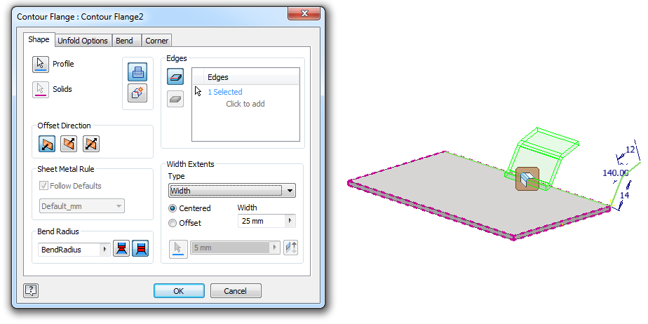
This dialog box will open.
Select whether you want to select just one edge, or a loop.
Circled in the image below is:
Edge Select Mode: Which will allow you to select only 1 edge.
Loop Select Mode: Which will select all edges when you select an edge on a face. This will also apply corner seam to all corners where flanges meet. If you apply 1 Flange at a time, using Edge Select Mode, this will not apply Corner Seam. You will have to apply the Corner Seam feature after the Flange feature.
Then select the edge, edges you want.

Then select the offset direction you want he Sheet Metal to be. Which side of the open profile the Metal gets applied to.
Bend Radius
Change Bend Radius if needed.
Width Extends
Width Extends only works if you select one edge.
Edge
Places the Contour Flange all the way along the edge you have selected.

Width
Centered (Width)
Places the Contour Flange in the middle of the edge you select. Then the width of the Contour Flange is determined by the dimension you enter.
Offset (Width)
Places the Contour Flange offset from the edge you select. Then the width of the Contour Flange is determined by the dimension entered.

Offset
Places the Contour Flange an offset distance from 2 points you select. In the picture below i have picked the 2 edges of the steel. Which i have circled. And offset by 10 mm. So the Contour Flange will start 10 mm in from the 2 edges i selected.

From To
Places Contour Flange From a point you pick. To another point you pick. In the example below i have chose the edge of the steel. And a work plane. So my Contour Flange will start at the edge selected, and end at the work plane. I have circled the points i picked.

Distance
Distance places the Contour Flange the distance you type in the box. In the example below i have placed 50 in the box. So the Contour Flange will be 50 mm long.

Offset Direction
Offset Direction lets you choose which side the put the material on. As shown below.


Both sides of the line

Change which side of the profile the Contour Flange is placed
I will show you how to change the side of the profile the Contour Flange is placed on.


Both sides of the profile.

Thanks for reading,
Thomas Savage


Comments
Post a Comment